Авторизация
Сейчас на сайте
Счетчики
How to check radio components?
How to check radio components?
Before soldering parts into the structure, they need to be checked. You already know how to check the resistors - just measure their resistance with an avometer operating in ohmmeter mode.
In the same mode, capacitors and diodes are checked. In the first case, the probe of the avometer is placed in the socket “X1000” of the ohmmeter (the second probe, as was shown earlier, is always in the socket “*”) Touching the probes of the capacitor leads, measure the resistance. Then the probes are interchanged and the resistance is measured again. In both cases, it should be very large (because the capacitor does not pass direct current) - the arrow of the indicator should remain in the extreme left position. When checking large-capacity capacitors, the arrow may sharply deviate at the initial moment, and then return to its original position. This is explained by the fact that at the initial moment of connecting the probes to the terminals of the capacitor, a current surge passes through it briefly enough to deflect the indicator arrow. The larger the capacitor, the greater the deflection of the arrow.
Electrolytic capacitors (especially with a capacity of more than 10 microfarads) are checked by inserting the probe into the "x100" or "x10" socket. The indicator arrow when touching the capacitor leads sharply deviates to the right and gradually returns. When changing probes in places (that is, when changing the polarity of the ohmmeter connection to the capacitor).
The arrow deviates even more sharply to the right (after all, the capacitor was charged during the first measurement) and again smoothly returns to its original position or shows some resistance - it should be as much as possible. If the resistance of the capacitor in both cases of measurement is so small that you have to go to the limit "X1", such a capacitor can not be put in the design.
Diodes check, like capacitors, with two polarities of an ohmmeter connection. With direct polarity (when the "common" ohmmeter jack is connected to the anode of the diode), the arrow of the indicator should deviate, but with the opposite - no. The resistance of various diodes with direct and reverse polarity can vary by tens, hundreds or even thousands of times. The more powerful the diode, the less its forward and reverse resistance.
The windings of transformers, inductors, headsets, dynamic heads are checked when installing the probe in the sockets "X1" or "x10".

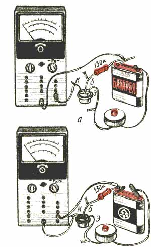
Fig 1 transistor current transfer measurement
Transistors are checked by measuring their current transfer coefficient. In addition to the avometer operating in the current measurement mode, you will need a 3336L battery with a voltage of 4.5 V, an MLT-0.5 resistor with a resistance of 130 kOhm and a bell button.
If the transistor of the structure is p-n-p (MP39-MP42, P401-P403, P416), the details must be connected to each other in accordance with Fig. 1 a. The transistor leads are connected by soldering or twisting. The gauge probes insert 3 milliamps into the DC measurement jacks. In this case, the indicator scale (lower) will be designed to measure the current transfer coefficient up to 90, that is, each division of it is equal to 3.

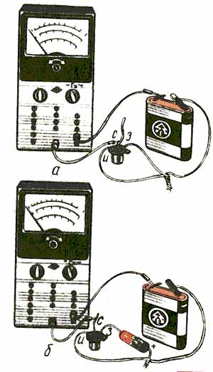
Fig. 2. Checking the field effect transistor: a - measurement of the initial drain current; b - connecting a galvanic cell to reduce the drain current and there will be a current transfer coefficient of the transistor
The transmission coefficient measurement limit of 90 is selected based on the use of the most common low-power transistors in our designs. If there are transistors with a high transfer coefficient and the arrow of the indicator DECLINES for the final division of the scale, replace the resistor with another one, for example, 430 kOhm resistance, then the measurement limit will increase to 300. When measuring, first press the button briefly. If the arrow of the indicator sharply deviates for the final division, release the button and rearrange the probe in the socket “30”. If here the arrow is outside the scale, then the transistor is faulty - it is broken and a short circuit has occurred between its terminals.
If the indicator arrow deviates within the divisions of the scale, hold the button pressed longer and follow the behavior of the arrow. It stands still - the transistor is good, it “floats” in front of our eyes (that is, its indications are smoothly changing) - the transistor is of poor quality, and it is impossible to put it in the design.
To check the transistors of the structure pnp, you need to connect the parts in accordance with Fig. 1 b As you can see, the polarity of the battery and the polarity of the inclusion of the probes of the avometer are changed. Everything else is as in the previous case. According to the same schemes, transistors of medium and high power can be checked. But the resistor should be much less resistance - 4.3 kOhm. And the avometer should be switched to the measuring limit of "30". Then the entire indicator scale will be designed for a current transfer coefficient of 30, which is quite enough for most of the transistors used in our designs.
If there are transistors with a high transfer coefficient, there is a simple way out - rearrange the probe of the avometer in the socket "300". Now the indicator scale will be designed for a current transfer coefficient of 300.
And how to check the field effect transistor? The required parameters are not specified in the design descriptions. But it does not interfere with checking the transistor before installing it on the circuit board. To do this, use fig. 2a, connecting a transistor, a battery and an avometer, operating in the current measurement mode (at a limit of up to 3 mA). The avometer indicator should immediately show the current, which is called the initial drain current. Then turn on a 1.5 V galvanic cell between the gate and the source (Fig. 2, b) - the drain current should decrease. If so, the transistor is working.
A similar test circuit is suitable for transistors of the KP303 series. If you have to check the transistors KP103, the polarity of the battery, galvanic cell and probes of the meter must be reversed. It may happen that the arrow of the avometer deviates beyond the final scale division when the drain current changes. Then you need to switch the device to another measurement limit.
***


Letzte Kommentare
Artikel
Fotos
Eigene Seiten